 EZMaker3D
Why rehearse the workflow before making parts?
A manufacturing chain can look complete while still hiding unresolved interfaces. A board outline may not match the enclosure. A lid may slice correctly but lack a machine-ready tool definition. PLC logic may compile while the real I/O map remains unknown. This study treated those uncertainties as first-class results rather than filling them with optimistic assumptions.
The goal was not to claim a finished product. It was to test whether a repeatable, offline workflow could carry one concept through several engineering tools while preserving clear release boundaries.
Workflow at a glance
1. Mechanical PCB reference
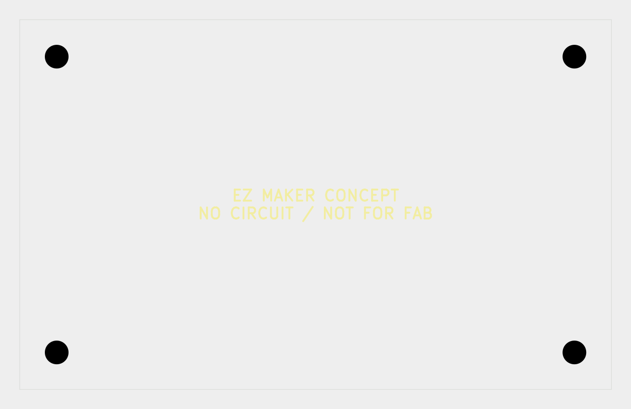
A two-layer, no-circuit board outline was used strictly as a mechanical reference. The digital check confirmed an 80 × 50 mm concept outline, four mounting holes, no nets and no routes. Mechanical DRC, SVG and STEP exports completed successfully. Because no electrical schematic existed, this was not an ERC-validated electronics design and was not suitable for fabrication release.
2. Enclosure CAD and additive preparation
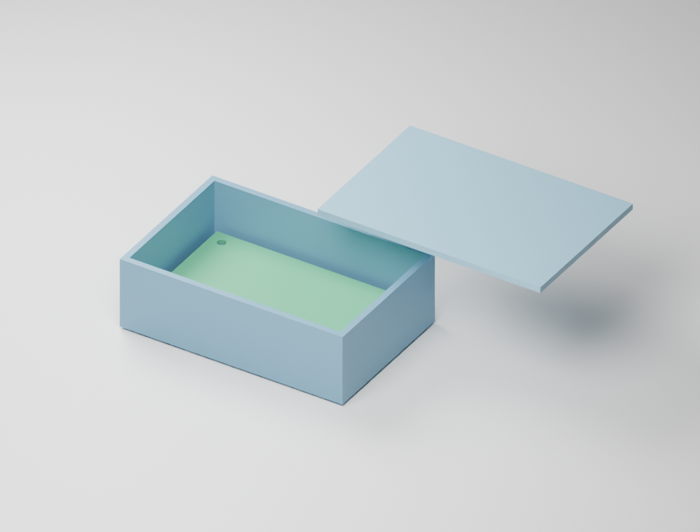
The enclosure model produced three solids and passed a STEP read-back check for the four mounting features. The concept used a 90 × 60 × 28 mm base and a 90 × 60 × 2.4 mm lid. Those values were design assumptions, not measurements taken from a finished development board.
Base and lid were packaged as separate 3MF files and sliced with a default offline profile. Successful slicing proved that the geometry could enter a print pipeline; it did not prove printer compatibility, tolerances, material behaviour or assembly fit.
3. CNC simulation and logic checks
A same-size lid was passed through an offline CAM and material-removal simulation. The log exposed a useful warning: no current tool had been defined, so the simulator selected tool 1. That is exactly the kind of issue a rehearsal should reveal before a machine is involved.
The PLC portion compiled structured-text logic and exercised truth-table and rejection tests through an offline API. It did not validate a PLC runtime scan, physical I/O, wiring or fail-safe behaviour.
Evidence, assumptions and open work
| Verified digital evidence | Design assumptions | Not tested |
|---|---|---|
| 12 offline stages completed; mechanical exports, CAD solids, 3MF packaging, slicing, CAM simulation and logic tests produced recorded outputs. | 80 × 50 mm board reference; 90 × 60 × 28 mm base; 90 × 60 × 2.4 mm lid. | Real PCB production, printing, CNC machining, physical assembly, dimensional inspection and machine safety. |
| Four mounting holes were read back from the STEP reference; backend regression and missing-tool blocking tests passed. | Component envelopes, connector positions and openings remained provisional. | Electrical schematic/ERC, real component layout and routing, PLC runtime I/O, power and thermal behaviour. |
What the study caught early
- A mechanically valid board outline is not an electrically complete PCB.
- A successful slice is not evidence of print quality, fit or material suitability.
- A CAM simulation needs an explicit tool, stock and machine-specific review before machining.
- Compiled PLC logic does not establish safe physical I/O behaviour.
- Unknown inputs should remain visible instead of being converted into invented certainty.
Practical takeaway
The most useful outcome was not a render or a toolpath. It was a traceable chain that could say where evidence ended. For small workshop projects, that discipline makes iteration faster: assumptions can be replaced one by one with measured board dimensions, confirmed connector locations, chosen materials, printer settings, cutting tools and real inspection results.
The next responsible step is to freeze the actual electrical and mechanical interfaces before any production file is treated as final.
Study records
- Offline manufacturing workflow validation record — 23 October 2026
- Project consistency and release-boundary report — 23 October 2026
- CNC material-removal simulation log — 23 October 2026
- PLC compile and logic-test record — 23 October 2026

 Email